ABSTRACT
This paper describes a recently developed plasma source utilizing a combination of radio-frequency energy and thermionic-field emission to generate electrons with broad energy distribution, thus enabling the efficient generation of neutralized plasma. The unique modular construction of the source, low profile design and spatially tunable plasma distribution makes it retrofitable to a wide range of coating chambers.
The variable plasma geometry can be controlled independent of ion energy and current density. Specific usage of the source for assisted deposition of optical coatings is described.
INTRODUCTION
The past decade has seen a revolution in thin film coating technology, one facet of which has been the development of so called energetic processes such as ion and plasma assisted deposition. Such ion or plasma assisted processes can be effectively used in vacuum processing of thin film coatings during electron beam or thermal deposition.
The energy imparted by the source to the growing film is capable of modifying the microstructure producing dense, near stoichiometric films that are impervious to temperature and humidity variations. Thin film deposition in the presence of energetic neutral ions imparts additional energy to the growing film, resulting in increased densification, spectral stability and general durability of optical coatings. The refractive index achieved is near that of the bulk materials, thus extending the possibilities for multilayer thin film design.
Plasma/ion assist sources are also exceptional for in situ substrate cleaning. In particular, argon cleaning provides physical sputter removal of adsorbed water and residual cleaning solvents. Oxygen cleaning can stimulate chemical removal of hydrocarbons through the formation of volatile species.
There are a variety of plasma and ion sources available, all of which rely on generation of electrons confined within a magnetic field to stimulate ionization of a working gas. Neutralization of the plasma is required to avoid charging effects and localized discharges within the vacuum chamber.
Initial ion assisted processes utilized gridded ion generators1-3, usually based on Kaufman-type designs originally developed for use as space thrusters4. However, such designs are limited in relation to the extent of the ion flux and extraction of low energy (<100 eV ion energy). The end-Hall ion source5 addresses this problem by providing a relatively broad beam (30° half angle) and low voltage operation, providing lower energy ions for effective assisted deposition6. Plasma ion assisted deposition7,8 utilizes a dc voltage between an anode and a hot cathode, creating a high-density plasma that is extracted via an electromagnetic field. This configuration provides wide coverage over a large substrate area. The primary advantage of the plasma compared to the ion source approach is that the plasma fills the vacuum chamber and couples into the evaporant, inducing partial ionization.
Neutralization is a key requirement for plasma sources. Insufficient supply of free electrons can generate space charge effects, which spreads the plasma, and also introduce edge effects for dielectric substrates mounted in metal holders. This manifests itself as a film thickness variation.
The plasma source described below overcomes some of the problems outlined above, and its construction and installation flexibility allows it to be retrofitted into different coating system configurations.
DESCRIPTION
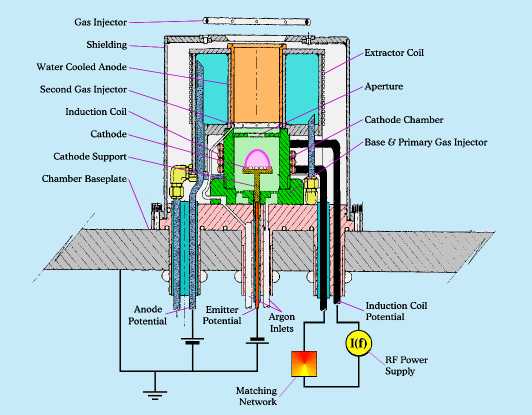
As shown in Figure 1 the plasma source has a modular construction thereby providing various emitter configurations and output electromagnet coil geometries to tune output plasma current density and spatial distribution for specific process requirements.
The source incorporates a thermionic emitter material heated by an induction coil, which also provides radio-frequency energy within an electrically insulated cylindrical former. A cylindrical anode is concentric with the emitter and axially displaced, generating a potential difference between anode and emitter. The potential difference between anode and ground and axial magnetic fields causes the plasma to be extracted from the source.
Figure 1. Cross-section of the plasma source.
The domed emitter maximizes emission surface area while minimizing electron field discontinuities. Process gas is introduced near the emitter and a secondary gas is injected into the anode space.
Radio-frequency excitation of the emitter generates electrons via thermionic and field effects, resulting in efficient plasma generation. The field effect electron generation contributes to a broad energy spectrum of electrons, providing effective neutralisation of the plasma. Moreover, the induced time varying axial magnetic field in the vicinity of the emitter provides enhancement of plasma generation and confinement of the plasma to minimize emitter erosion.
The induced magnetic field is de-coupled from a time invariant electromagnetic field for separate control of source plasma spatial distribution. Spatial control of plasma flux at the substrate plane is additionally provided by the relative positioning of the output electromagnet with respect to the induction coil. A greater spatial spread of plasma flux is achieved for increased separation of electromagnet and induction coil.
Measurements of ion current density and ion energy were carried out with Faraday cups and Langmuir probes respectively. Figure 2a shows ion current density, for extremes of plasma source running conditions, as a function of spherical distance from beam axis for narrow (25° half-angle) and wide (65° half-angle) coverage. The ion energy typically corresponds to 80% of the anode to earth voltage. Typical ion energy of 80eV is utilised for assisted deposition of optical coatings.
Figure 2a. Current density profiles at a spherical source to target distance of 50cm using Ar for two extreme source running conditions. Source is located at centre of baseplate.
Variation of TiO2 refractive index as a feature of ion current density is shown in Figure 2b, indicating a threshold value at which constant refractive index is achieved. This result is in accord with the requirement for a minimum ion/adatom ratio to achieve film densification for a given material deposition rate.
Figure 2b. TiO2 refractive index as a function of ion current density (TiO2 deposition rate = 5.5Å/sec.).
EXPERIMENTAL RESULTS
Experimental work was performed in a standard production box coater equipped with a plasma source located halfway between the centre and edge of the baseplate. The chamber was pumped by a 4,200l/s diffusion pump. Film thickness and deposition rate monitoring was via a commercial deposition controller. Two 12kW electron beam evaporators were used for the coatings.
Properties of single films of titanium dioxide (TiO2) and silicon dioxide (SiO2) were characterised using various plasma conditions and material evaporation rates. Multilayer edge filter coatings and broadband anti-reflection coatings were investigated by fabricating them using the optimal parameters found from the above. Room temperature plasma assisted deposition of MgF2 has been demonstrated. Results are described as follows.
TiO2 deposition
TiO2 films were evaporated onto borosilicate glass witness pieces located across the 700mm-diameter substrate calotte, at various deposition rates. The spectral transmission curves were plotted and the refractive index and dispersion characteristics calculated. Figure 3 shows the transmission spectral curves. Spectral characteristics for non-plasma assist and substrates coated at 300°C are also included for comparison.
Figure 3. Spectral transmission curves for TiO2 deposited onto a hot substrate and cold substrates with and without plasma-assistance.
Refractive index achieved for plasma-assisted deposited TiO2 was 2.40 at 550nm. Plasma source running conditions shown in Figure 3 were: plasma current 40A, plasma voltage 112V and deposition rate of 3.5Å/sec. The refractive index obtained was independent of rate up to 3.5 Å /sec, demonstrating that sufficient ion to atom ratio had been achieved to produce fully densified TiO2. Above this rate the ratio changed to produce a lower index that was consistent across diameter of the calotte. For comparison, the index of TiO2 was 2.20 and 2.30 for deposition at room temperature and 300°C substrate temperatures respectively.
SiO2 deposition
SiO2 deposition was more difficult to characterise, as densification is manifested by a change in packing density rather than a refractive index change. SiO2 was calibrated using similar plasma conditions to TiO2, and fully dense films were achieved at a deposition rate of 5.5 Å /sec.
Multilayer edge filter
A calibration shortpass edge filter was designed using the dispersive indices calculated from the material spectral data. Coating runs were performed and the spectral performance assessed against the theoretical design. Close agreement between theory and practical results were obtained, and the blocking bandwidth achieved was within 0.8% of the theoretical predictions. This indicated that the theoretical index and dispersion models of the individual materials were correct.
Figure 4. Spectral edge transmission at room and elevated temperatures.
One additional feature observed was the lack of fringe edge effects near the substrate support. This is thought to be due to the presence of low energy field effect electrons that neutralise the plasma space charge in the vicinity of the substrate. Lack of neutralisation here can distort the electric field near the substrates, resulting in film thickness variations where the substrate is supported by the metal surround.
An independent test house assessed thermal stability of the coated samples. They confirmed that the spectral edge position was identical when measured at room temperature and 250°C. Spectral transmission characteristics for the SiO2/TiO2 multilayer coating, measured at room temperature and 250°C, are shown in Figure 4. A slight increase in transmission in the blue region of the spectra was evident after baking. This is consistent with other plasma-assisted processes and is thought to be caused by realignment of O2 molecules at layer interfaces, rather than due to non-stoichiometric TiO2 structure.
The coated filter was subjected to adhesion tests, severe abrasion, extended humidity and immersion in boiling water for several hours. No deterioration was observed. Single layer SiO2 and TiO2 and SiO2/TiO2 multilayers pass the environmental and abrasion requirements of MIL-C-675C.
MgF2 deposition
Ion and plasma assisted deposition of magnesium fluoride (MgF2) for single layer anti-reflection coatings has always been problematic due to the low dissociation energy of MgF2 and its affinity to react with oxygen. The resultant film manifests itself as an MgO:F compound, which is soluble in water, rendering it useless as a durable single layer anti-reflection coating.
A room temperature process has been developed using a special pulsed plasma deposition regime that, to a large extent, overcomes this problem, and the resultant coatings have been extensively tested for environmental stability. The coatings have been subjected to repeated severe abrasion tests, adhesion, and salt-water immersion for several days, without deterioration. The coating is currently undergoing environmental trials on CR39.
Other coating materials
Trials have been carried out for aluminium oxide (Al2O3) and tantala (Ta2O5). Results for tantala show an index value of 2.06 at 1500nm, which has application in DWDM telecoms filters.
CONCLUSION
A new versatile plasma source has been described for plasma-assisted deposition of thin films. The unique generation of sufficient electrons and corresponding ions overcomes one of the problems associated with plasma sources: insufficient space charge neutralisation which can manifest itself as film thickness variations (fringe effects) close to substrate supports.
The variable plasma geometry can be controlled independently of ion energy and current density, and the flexibility of installation makes it retrofitable to a large variety of coating system configurations.
REFERENCES
1. P.J. Martin, H.A. Macleod, et al, Applied Optics, Vol. 22 (1), 178-184, 1983.
2. J.J. Cuomo et al, Handbook of Ion Beam Processing Technology, NOYES PUBLICATIONS, New Jersey, 1989.
3. B.G. Bovard, Thin Solid Film", Vol. 206, 224-229, (1991).
4. H. R. Kaufman and P. D. Reader, Am. Rocket Soc., 1374-60, (1960).
5. H.R. Kaufman, R.S. Robinson, and R.I. Seddon, J. Vac. Sci. Technol, A5 (4), 2081-2084, (1987).
6. M.L. Fulton, SPIE, Vol. 2253, 374-393.
7. K. Matl, W. Klug and A Zoller, Mater. Sci. Eng., A140, 523, (1991).
8. S. Pongratz and A, Zoller, J. Vac. Sci. Technol., A10 (4), 1897-1904, (1992).

Contact details:
Satis RTC Photonics Systems
Tel. + 44 (0)1767 313067
This page last updated on November 23rd. 2000 and is © Satis RTC Photonics Systems Y2000
Turnpike Farm
Potton Road
Biggleswade
Bedfordshire
SG18 0EP
England
Fax.+ 44 (0)1767 600331
Eml. sales@satisrtc.com